Thulani: How are you sir? I have encountered a problem with a Telefunken TV, l think the
problem is on RGB circuit, the picture is there, it shows three colors which is
red on the four corners, blue and green on the center screen. When l check the
main RGB volts 200v and on board is 180v.the RGB is from FBT
Showing posts with label Television. Show all posts
Showing posts with label Television. Show all posts
Saturday, December 10, 2011

Thursday, October 6, 2011
Sanyo color 21” model AMV-2136 Dead -Customer Support via email
Here is a small email I got from one of my CRT
Television repair course customer.
Good day my friend,
i have a customer with Sanyo color 21"
model AMV-2136 ...
Problem: Dead on arrival
Remedy: After opening the Equipment. Fuse is totally black (blown)
Saturday, October 1, 2011
NEC TV 21” CRT sound not ok but picture Okay
This
TV was brought in my shop with the picture ok but the sound was not
stable…sometimes good and other times not.
I
opened the set and went straight to the speaker (power off and power cable disconnected
from the power outlet).
Saturday, September 10, 2011
Akira Television 21 Inch dead
Roger: sir good
day,,,,now I’m repairing a 21 inch,tv,akira,,,,the power regulator ic is
down,,,so i replace,,,,there is also a ceramic disc cap rated 222k is burnt
already at secondary side, beside output diode, so i replace,,,by the way the
fuse have burnt also,,,,so i power the set using light bulb,,,when i plug i
noticed the front led not lighted,,,,, what the area I’m going to check
sir,,,maybe the micro not power also,bcos,,no 5volts,,,,, by the way this tv is
using power ic,,,str g6653,,,even there is no 5volts ,I try to sw.on the
set,,and i can do voltage testing,,,the main cap is 300v,,,pin 1 of ic is 300v
also,,,,pin4 is about 14to 16v,,,,pls,advise me sir,,thanks,,roger
Humphrey: Any voltage on
the secondary side of the power supply?
Roger: sir, good day,,,i
continue checking at primary side, I bump to a resistor rated .15 ohms,,,its
reads 18k ohms,,,so i check the link of this low ohms resistor,,,it connected
to pin 2 of str g6653,,,it is a current sense resistor,,,that turn to high
ohms,,,i think this is cause why the power supply and also front led not
functioning,,,,,am i correct sir?,,,now im preparing to install a new low ohms
resistor,,rated 0.47ohms,,,,,because
0.15-ohms is not available,,,,maybe this tv is start working,,,,after i
replace total of 5 components,,,,,,by the way sir thanks,,,,,,i let you know
,after i fix this tv,,,,god bless,,,roger
Humphrey: 0.47 ohms is
still quite high for current sense resistor...use three 0.47 ohms resistors
connected in parallel to get 0.16 ohms for this circuit.
Roger: ok,sir ill do that your good advise,,,,i
will make 3 ,,,,,,,0.47ohms resistor in parallel,,,,thanks
Roger: sir good
day,,,,after i replace a e-caps at the vcc rail of str g6653,,,when i sw.on the
front led has come on now,,,,but i notice the light bulb is having intense light,,,,so
i check the voltage at the secondary diodes,,,all are ok,,,but the B-positive
is low,,,i disconnect the degauss coil,,,,check again the voltage at B-positive
its reads 112v,,,so i confirm the posistor is already short,,,,Because i check the degauss coil is ok,,,,now,,,all
the voltage output at secondary is present,,,,but the tv does not sw.on,,,,,the
front led is ok also,,,,,the micro is already powered,,,,but why the tv cant
sw.on ? so i check the condition of fbt,,,primary
winding is ok,,,,i powered again the set and check the fbt secondary
voltages,,,the 185v reads only 112v,,,,,,the screen voltages reads 3.2v,,,,,the
other fbt output no readout,,,,,so why this happen sir think the fbt is already
gone also sir? Even though the primary winding of fbt is ok? You know sir? I
learn a lot in this trouble-shooting,,,pls.advise me sir,,thanks,,roger
Humphrey: I don’t think
the fly back has a problem, I suspect the horizontal drive circuit, read your
book chap 10 for more details on testing and troubleshooting this circuit.
The Voltage of 112volts at the output of the FBT is same as
the 112volts b+ voltage because the fly back is not switching. So this leads us
to suspect a problem with the drive circuit. For example any voltage at the
collector of the drive transistor? How much?
Check that and come back to me please.
Roger: sir good
day,,,,,yes is true that the output voltages the same,,,,,,112v,,,,now my mind
is thinking so much,,,,I have read again the book at chapter 10,,,,,i think my
assumption is correct,,,to double check the horizontal drive circuit,,,,,,so i
confirm to you sir about your advise,,,,,,sir you know you’re a nice guru for
me,,,,,so i study hard for this field,,,,,especially CRT TV repair,,,,,big
thanks for your advise sir,,,,,i let you what the progress of repair
Roger: sir good day,,, I
check the horizontal drive circuit,,,,i power on the tv,,and test the voltage
at collector of h-drive transistor it reads 112v,i trace the line is coming
from the b-positive line,,,pass the two 10k resistor in parallel,,,,i check the
pulses at the base ,,i find dry joints,,,,so i re-solder the area of h-drive
and the pulses is ok,,, ,,,,now the set is totally power on,,,,sir you know I
have so much learn about your advises for me,,,,i have so many things in
trouble shooting that i have learn,,,,dos and don't,,,,procedures,,,the
principles that I learn in your book is giving me a inspiration to continue
learning this field,,,now my confidence is simply increasing,,,,,b-cous of your
support sir,,,,
Monday, August 15, 2011
REPAIR TV REPORT PARS GRUNDIG 21" COLOR TV PART –Dead part2
In the first part of this repair report by Mr. Beh, he promised to come back with his final report of what he did next to the Grundig 21” Tv which refused to have high voltage even after replacing the fly back with a new one.
No doubt Mr. Beh is back with his final report on this repair …


I started testing components on the same circuit and I found an electro cap in same circuit which was not good according to my meter and after replacing it the white line disappeared.

The Television is now happy and ready for collection by the customer.
No doubt Mr. Beh is back with his final report on this repair …
Mr. Beh tells us we are listening…….. After I changed the fbt of this Television with a new one I expected the Tv to start working but the TV did not work and therefore I did not have high voltage yet.
This TV has an ic on the drive circuit and I decided to Google it and see what is it all about, the reference of this ic was TDA8140, after searching the net for this ic this is what I got.
The TDA 8140 is a monolithic integrated circuit designed to drive the horizontal deflection power transistor। And here is the application circuit for the same.

From the datasheet above you can see no doubt this is a very important component as far as horizontal deflection circuit is concerned because it is actually the driver circuit.
So I decided to change it and this time the TV has high voltage and I was happy but wait a moment, the picture came up but with a vertical line at the middle.
I started testing components on the same circuit and I found an electro cap in same circuit which was not good according to my meter and after replacing it the white line disappeared.

The Television is now happy and ready for collection by the customer.
Thank you guys.
God bless You
By Mr. Beh.... An Electronics repairer based at Tehran in Iran.
Monday, August 8, 2011
REPAIR REPORT OF PARS GRUNDIG COLOR TV 21” MODEL 5593-DEAD
This article is brought to you by Mr. Beh. An Electronics repairer based at Tehran in Iran.
Initial facts:
The estimated age of this Television is around 12 years of continuous service, No circuit found over the internet.
First I have to tell this TV set was rejected by authorized repair center and brought to me Completely dead with no sign of life, After blowing the inside I checked the Big capacitor by analogue meter set on dc mode 300 v dc
My voltmeter confirms that the 300 volt dc is reaching to the pin of the main capacitor (The red probe to the Positive side of capacitor and black probe to the negative side of the BIG filter cap).
With this I concluded that that all components before the main capacitor like bridge rectifier on /off switch, AC cord are ok and therefore not considered for any further testing.
I checked pin no 6 of regulator ic this is TDA4605 ( by goggling I found the diagram of the ic and the Vcc of this ic that was pin no 6) the red probe of the meter was on the pin 6 and the black probe the negative pin of the Big filter capacitor.
My meter read nothing. Zero volts. Checking the pins of this ic and all surrounding component I found out that there were many cold joints in the low power supply area. I took time and re- soldered them all again.
After that I powered the set and checked pin no 6 of regulator ic and Yes! I got about 11 v dc in V cc pin of ic and is within tolerance. This means the set is getting all the important voltages but to my surprise still TV has no sign of life.
Then is decided to check the secondary side of smps. With my analogue meter I checked the voltages coming out of the smps. This TV has 5V output from the transformer and 5V Schottky diodes, by putting the red probe to the negative (Cathode) side of diodes and black probe to cold ground of the Television.
I checked them all one by one, the voltages were within tolerance and are ok and I was happy up to here. In old CRT TV, usually there are two components that bring problems.
1 HORIZONTAL OUT PUT TRANSISOR (H.O.T)
2 FLY BACK TRANSFORMERS
First I checked the H.O.T by putting my meter on ohm mode x10k (H.O.T in this set is BU508D). D means a diode also is installed in the transistor compartment
And the shape of pins from left to right when the face of transistor is up is B.C. E .And by comparing the reading of meter with new healthy transistor I put ok stamp on this H.O.T of this TV. But what else can cause this problem? The only card remaining is now the fly back transformer?
To test the fly back I used my home made fly back tester which was on my work bench, I checked the pins of this transformer comparing with a good fbt and I concluded that trans former(FBT) is not ok because checker showed two L.E.D were lighted.
Below you can see assembled homemade fly back transformer and expected result from a good fly back transformer (all L.E.Ds) are ON.

I changed with one I had in my salvage stock, After replacing the fly back still there was no high voltage ?...having used my last card I took a break…
See you on the next and last part of this intriguing repair experience
God bless all repairer
Beh
Friday, July 8, 2011
GLD Television with a single horizontal line
This Television belong to a Colleague of mine, She has a phone which she wanted me to check for her which was having some problems and in the course of our chat she told me that she also has a TV which is lying in her house and if I know a good technician who can look at it.
I asked her what does she mean by a good technician and told me she no longer have trust with technicians because of previous experiences with them…I did not like to go into details of her past experiences with techs and therefore I offered myself as a possible option if she wouldn’t mind.
She agreed but the condition was that I must repair it on site, I requested her, the possibility of me taking the motherboard alone with me for troubleshooting and repair in my workshop and come back to her to re-assemble the set in her house.
That option also didn’t work and therefore having no other option left for me, I decided to do it on-site (while – She - wait). Besides from the description she gave, I knew it is not a major assignment as you know with single horizontal line on the screen that directly point to a problem on the vertical circuit.
So I gave her an appointment for the following day after work, in preparation for the day I took a small digital meter(the eyes of the technician), a screw driver, half feet long solder wire, solder gun, solder sucker and a side cutter and placed them in my on site traveling bag.
Also because from my experience with these China made TVs I carried with me some two Capacitor rated 1000uF/35v and 470uF/35v. Both capacitors filter the vertical supply power and they have a very high failure rate.
Come the appointment day and I went to her place ready for the task ahead. The television was brought on the dining table which for now was to serve as my repair work bench.
As usual I had first to power the TV on to confirm what she told me and also to get any other clue from the screen itself. After powering on, the TV came up and indeed there was a horizontal line across the TV screen.
Looking at the line keenly I could see the line was not smooth but had some waves like on the sides. This could points to dry joints or loose connections around the vertical circuit. I tapped the Television softly with my bare hands and the line (horizontal kept on changing) which further indicated the possibility of dry joints.
I opened the set and did some scanning on the secondary side of the power supply on the component side and I didn’t see any suspicious component, then I turned the board to the bottom side and went straight to the vertical ic (LA 78040)

Without magnifying glass I could see two big dry joints (I mean like pot holes on pin 2 and 6 of this I.C LA78040) below is the datasheet of this ic.


Looking at the datasheet above you can see pin 2 and 6 supply this ic with the much needed 27 Volts supply from the secondary of the power supply.
The 27 volts goes through a diode and it is split into two, one line goes straight to pin 2 and the other goes to pin 6 always through a diode and therefore expect a small drop across this diode of about 0.7 volts (so the voltage at these two pins will be almost equal (+ or –) 0.7 Volts of each other.
The 27 volts goes through a diode and it is split into two, one line goes straight to pin 2 and the other goes to pin 6 always through a diode and therefore expect a small drop across this diode of about 0.7 volts (so the voltage at these two pins will be almost equal (+ or –) 0.7 Volts of each other.
After re soldering all suspect areas it now time to power up…usually after repair I like powering the set via series limiter bulb but because I never carried it to the site I had to do it directly.
I pressed the power ON button and nothing happened. Even the horizontal line is not there…DEAD. I tried to listen to the signs of life from the TV and I could hear some sound from the secondary side of the television.
What could have happened now? I figured out that because this TV was having a horizontal line before and now it’s not powering on it could mean that there is something I have done wrongly in the course of this repair…and the most probable thing could be while I was Re-soldering the dry joints I could have shorted a components pins or path because the light was not enough to see the solder are perfect.
So without the magnifying glass I used my meter set to continuity range to try to locate the shorting path/component pins. There was a connector I had re soldered and I went straight there to confirm if it was ok. After testing the two pins I could hear the meter beep (the connector had three pins and all the three had beep)
After further investigation if noticed this is connector for 180 volts RGB supply, heater voltage and heater ground. The heater pin and ground should have a beep but not for the 180 volts. So did some cutting between the heater supply pin and the 180 volts supply until I heard no more beep.
Again I powered the TV and this time the TV didn’t disappoint me…it came up nicely.
A word of advice to new technicians.
I would not advice you to repair equipment at the owner place unless you are very confident with yourself.
You can easily forget and discharge one of those BIG electrolytic capacitor with a screw driver and with the sounds it makes and the sparks generated you might find everybody running out of the house with the fire alarm already activated for fire fighters to come in to put the fire out which they perceive you have caused.
Wishing you all happy repairing.
Humphrey Kimathi
Author CRT Television repair course
Wednesday, May 25, 2011
JCV Television Color problem
This Television came in for repair with the screen color purple, please note that this in not JVC and it’s not even a typing error. It is simply JCV, that’s why as a buyer you should always be keen when buying electronics gadget because some of them come with a name very close to a branded one.
A brief history from the owner was that the television works for a few minutes with normal color and after sometimes the screen color changes and he suspected the tube is faulty( I advice technicians to listen carefully to the customer history of the problem but when it come to suggestion where he think the problem is.. be wary)
I powered up the set to confirm what he has said and truly the set came up and after 5 minutes the color was messed up again. Looking at the screen I could see the problem pointed at the RGB circuit.
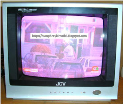
I opened the set and went straight to the suspect circuit and scanning around this circuit I could see the three RGB transistor (2SC2482) are all darkened on the board. This pointed to overheating and in the meantime I decided to take the voltage around this circuit.

I did the voltage testing and all the three cathodes were within the expected range. Then I remembered one clue the owner gave me was that the problem was coming up after sometimes and I reasoned most likely there could be a component which is getting overheated and hence start behaving funny.
So I used my finger to touch the three BIG resistor which take 180 volts to the collector of each transistor (Drops 180 Volts to around 145 volts at the collector of the RGB transistors)
Two of them were extremely hot for my finger and I concluded there could be a component failing under load and the most likely culprit could be the two transistors after these resistors. Luckily I had a junk board and I salvaged the two transistors and used them in this assignment.
I powered the set and it came up smiling again as you can see the picture below.

Thank you guys
Let meet in the next class
A brief history from the owner was that the television works for a few minutes with normal color and after sometimes the screen color changes and he suspected the tube is faulty( I advice technicians to listen carefully to the customer history of the problem but when it come to suggestion where he think the problem is.. be wary)
I powered up the set to confirm what he has said and truly the set came up and after 5 minutes the color was messed up again. Looking at the screen I could see the problem pointed at the RGB circuit.

I opened the set and went straight to the suspect circuit and scanning around this circuit I could see the three RGB transistor (2SC2482) are all darkened on the board. This pointed to overheating and in the meantime I decided to take the voltage around this circuit.

I did the voltage testing and all the three cathodes were within the expected range. Then I remembered one clue the owner gave me was that the problem was coming up after sometimes and I reasoned most likely there could be a component which is getting overheated and hence start behaving funny.
So I used my finger to touch the three BIG resistor which take 180 volts to the collector of each transistor (Drops 180 Volts to around 145 volts at the collector of the RGB transistors)
Two of them were extremely hot for my finger and I concluded there could be a component failing under load and the most likely culprit could be the two transistors after these resistors. Luckily I had a junk board and I salvaged the two transistors and used them in this assignment.
I powered the set and it came up smiling again as you can see the picture below.

Thank you guys
Let meet in the next class
Humphrey Kimathi
Author CRT Television repair course
Saturday, March 26, 2011
Akira Television Dead
First I checked the status of the fuse and surge limiter. The fuse passed the test with flying colors and the surge limiter did not make-it was Gone according to my resistance test meter.
Now whenever you find the fuse or the Surge limiter gone as I have said it before, let me repeat it for those who are new in my class Please never replace any of these two components without checking the cause why they had to blow unless you want to keep the manufacturer of these two safety components in the business by buying their products.
 |
| click picture to view bigger version |
Therefore if you find the fuse or surge limiter has gone suspect a heavy short on the primary power supply components. On the high list of suspect is the chopper transistor- So I went straight to this transistor and sure it was dead short collector-emitter junction.
I replaced the chopper transistor and the surge limiter and because I still suspected some more short on the supply I put the television on using the series current limiter bulb.( Those who have already bought my CRT TV repair course e-book knows how valuable this small gadget is in terms of saving your new replaced components from shorting immediately after replacement).
 |
| click picture to view big version |
On power ON the series bulb never lit, I checked the voltage at the collector of the chopper transistor and was present, around 300 vdc but none at the base.
If you find no Voltage at the base two things may have happened.
1. Either there is an open component on the start-up path usually the start-up resistor or dry joints or even circuit broken.
2. There is a shorted component at the base of chopper transistor which is taking the chopper transistor base directly to the ground. See diagram Transistor 2SC3807 or capacitor across this transistor
 |
| Click photo to view bigger version |
In most cases it is the transistor which gets shorted and therefore starts by testing the condition of this transistor c3807 and finally the cap517.
You can even lift up the middle leg of this transistor c3807 and if you can now get some voltage at the base of chopper transistor (v513) then you can conclude that this transistor c3807 is shorted.
In my case I set the meter on the diode test (continuity) and tested between the two legs of capacitor c517 and the meter buzzer rang indicating to me that there is a shorted component across that path.
I removed one leg of capacitor c517 off the circuit and still I had a short reading on the meter. Finally I removed transistor v512 (c3807) and the short disappeared indicating to me that this transistor was also shorted.
I replaced the transistor and powered the set and the power supply was restored.
But still there was a problem because the TV was coming up and down. I was still using the series bulb and whenever the Television was shutting down the bulbs were very bright indicating some problem on the secondary side.
Then I decided to tap the set a bit on the side with my hands to see if there were any dry joints remaining but nothing happened.
Then I decided to tap the CRT neck board circuit with the back of the screw driver and I noticed the screen kept on changing. I checked it keenly and I noticed a lot of dry joints there too.
So what has this to do with the narrow screen? This is because the RGB amplifier voltage source is coming directly from the primary supply and hence a problem on the neck board circuit can even cause the power supply to drop or even block it completely.
So a Technician who is ignorant of how that Television work may spend up to two weeks looking for a faulty components on the power supply whereas the problem is at far end on the small CRT neck board circuit and end up being frustrated enough to send the Television back to the owner with the very unpleasant word to the Customer” Not able to repair due to lack of spare parts”
After re soldering the CRT neck board the screen was now full width and there was sound but no picture…..To be continued…..
Wishing you all the best Guys
Let meet in our next class
Let meet in our next class
Wednesday, February 9, 2011
Solving White lines problem in upper part of the screen of SONY TV MODEL KV 2199 PART -2
Solving White lines problem in upper part of the screen of SONY TV MODEL KV 2199 PART -2
In the last Article Part 1 of the above Television repair, Mr Beh promised to come back with part 2 of the same Television and maybe you were wondering what is it for if the machine worked…
This is because even if the television was up and running it was not 100% because if you were keen you could see some white lines across the upper part of the screen.
In this article you are going to see the power of term work and networking at its best in the following case…
By the time that report was being published this conversation was still going on in the background.
Mr Beh: DEAR HUMPHREY thanks you so much of your encouragements. But still this tv has problem with screen i have three big horizontal line in the screen in the top. Also you can see on that picture that i sent you. The picture tube also is suspect. The case is under process i will send you the result as a second report of this tv. Today i will have consultation with another repairer friend about this case. Kind regards beh
Humphrey: Hi Beh, Those horizontal lines point to bad capacitors around the ic...check the esr of those cap first.... Humphrey
Mr Beh: HI HUMPHERY thank you for your suggestions. Yes i check all caps except very small ones less than 1 micro i did not found any thing also i do not have any equipments to check the esr less than 1 micro any way thank you
beh
beh
Humphrey: sure there is no meter to test cap esr less than 1 micro......i can see your frustration on your face man...
i have been there many times and back....am telling you the experience you are getting is for life time...
finally please see attached file for more info....also be sure to re solder all components around that ic.
Best luck
i have been there many times and back....am telling you the experience you are getting is for life time...
finally please see attached file for more info....also be sure to re solder all components around that ic.
Best luck
Humphrey
And with that a little background of the events let join Mr Beh for round two of this Sony television repair...
In the first part of this report I explain repair of the power supply and TV start to work. But the TV was not fixed completely because of white lines in the Upper part of the screen.

This problem could be of following
1-the weak picture tube (The solution for this problem is costly the new picture tube is around 65 used).
2-another probable problem is in the G1 circuit of picture tube.
3- the defective caps around circuit of the vertical ic LA-7830.
i concentrate on G1 circuit and I did not found any problem in that section. Mean while I received some information from MR KIMATHI he sent
me the diagram of LA ic and (suggest me to check the cap strongly)

I start to check this Electrolytic cap 100 micro@ 35 volts. I pull it outside the board and I check with ESR meter the meter showed infinity but meter must Show at most 0.5. Also I check the cap by capacitor tester .tester must show something near 100 micro farad but Showed only 0.481 microfarad. I assume that the cap must be culprit .by changing the cap with new one the TV starts to work with no white line in the upper side of screen and white horizontal lines disappeared. Thank you MR KIMATHI for your on time info.

White lines are disappeared from upper portion of screen.
In Conclusion by Humphrey
From this article one can learn two very important principles about life:
Principle 1: Important of giving
Here giving does not necessarily mean giving money but all kinds of giving may it be time, sharing ideas etc..let take a look at the analogy with a river…A river always flow giving water to other small rivers until it finally give everything into the ocean and see rivers are always fresh and never dry up. On the other hand the ocean only receive water fresh water from rivers but because they don’t give out they remain salty forever…here mr Beh decided to follow the river model and shared his idea to the whole world and in the meantime got refreshed by being given an idea which maybe if he never shared this with us it could have taken him long to know.
Principle 2: Principle of Team work.
Another important one…here let me use another analogy..it is said that the power of 3 men combined is more that each man added together…you ask how can it be mathematically…let me explain with an example…let assume you are driving a car with 3 strong men and all of a sudden the car stop and therefore need a push to start..So the three men get out of the car and the first guy one by one start pushing the car…one man… no stat. And the second man...No start. And then bring in the third man and there you go the car now starts.
So we can conclude that mathematically the force of the three men is more than the force of each man individually and hence you can see why you should think teamwork in your next assignment.
thank you guys
let meet in the next class...
Monday, February 7, 2011
SONY TV MODEL KV 2199 M5T REPAIR -part 1
This report is brought to you courtesy of Mr Beh...We at humtech electronics take this opportunity to thank him for sharing with others...hope this report will encourage others to share their experiences also.....
I received this TV from one of my friend to repair. It is 10 years old and No diagram was found. The problem of TV was no power with pilot lamp on and fuse was not blown.
I used voltage testing method for repair of this set:.

Entrance AC voltage to bridge rectifier (LN4SB60) was good also 320 v dc On two poles of big cap mentioned that the big cap is running well. by assistance of goggle I found out that the vcc For STR (STRS6707) Must be 15 v DC but the voltage on the ic vcc pin9 was 7.5 v dc and This indicate that STR could be leaking the voltages

after changing The STR with new one the TV start to work but just for few seconds.(the sound was good ).

I check all other parts around second part of SMPS .also big transistor (HOT) of set was not giving good answer under test by volt ohmmeter (D1787). After substitution with (D2025) TV started to work steadily. But still no picture and only three Horizontal line on screen. This means no vertical deflection I proceed to vertical deflection ic in vertical section of the set it was hot like hell and also a big crack on the face of ic was visible this is (LA7830).

After changing this ic TV start to work also I got the picture very clear and sharp.

i want to mention that during the work on this TV I used isolator transformer for more safety
Wednesday, January 12, 2011
Understanding the Degaussing coil in CRT television
Understanding the Degaussing coil in CRT television
CRT Television and monitor are affected by the Earth magnetic field and for this reason Engineers designed the degaussing coil in order to take care of this effect which is usually manifested by colored spots on the screen.
Besides the magnetic field caused by the earth there are also other causes like placing strong magnet near the CRT television and therefore it is advisable to keep Speakers away from the set, usually when you find a television has spots on the screen first be sure there is no speaker or big radio(speaker inside) near the set.

One cannot talk about the degaussing coil without mentioning the Posistor(PTC). This is because since degaussing coil has very low resistance and is directly connected across the AC power line(240 Vac or 110 Vac) then it would create a short circuit across the power line but this is not so thanks to the Posistor(PTC) which is connected in series with the degaussing coil and when power is switched on the Posistor which has low resistance when cold but very high resistance when hot and therefore the coil will Pass current just for a moments before the Posistor get hot and cut off the current trough the degaussing coil.

Effect of the power supply when the Posistor fail:
1. Open - No effect on the power supply, only lose the demagnetizing effect of the degaussing coil (picture with spots)
2. Short - If the posistor shorts it means the coil will create a direct shot to the power supply and therefore fuse will blow.
In conclusion I wish to encourage technicians to take time to check the circuit diagram in order to see how the component is positioned (series or parallel) to the supply because by this one can be able to conclude the effect that component can have if it fails shorted or open.
Thank you guys
Let meet in the next class
Friday, December 3, 2010
Goldstar TV vertical partially closed
This Goldstar television came in with the customer complains the picture has a problem…so I powered the television to confirm his report.
As a technician it is very important to confirm what the customer has said in his presence otherwise the set might have gone to another technician with no color symptoms and when the customer picked it from technician A he/she didn’t bother to check the condition after staying at this technician A for six months with the usual excuse of lack of spares.. And was just returned to the box and brought to technician B who in this case happens to be you.
No color symptoms you have figured it is not a big deal and therefore you will hold it a bit to attend more serious repairs...so two days later you decide to work on that set with no color.
So you apply power with your eyes fixed on the screen to confirm what the customer told you two days ago. Pressed POWER ON button and nothing happens.
Checking on the power outlet it working well and therefore you decide to open the set to see if the fuse is gone and when you finally open the television you notice the fuse is okay but a lot of the circuit has been tampered with and components even missing including the microprocessor, you know how much it cost in your local currency.
Just when you have confirmed the above here comes the customer coming to see the progress of the set and as you begin to thank him for coming your way so that you can show him how his set was abused by the previous repairers he tells you that he only knows you and if you are not able to fix his set just bring it back the way it was with” NO COLOR SYMPTOMS’. Or he calls 911.
These things happen and if they have not happened to you yet please take my advice otherwise history does repeat itself.
So I applied the rule above and I switched on the Goldstar television and I observed the following:-
1. The set came up beautifully and I noticed the picture was partially closed with a black slip below and on top of the screen.

2. Sound was okay.
As a technician you can make a lot of conclusion just by watching the screen if you have a good knowledge on how that equipment circuit works.
A: There is something on the screen in our case CRT television. This means the primary power supply is okay, horizontal drive circuits is okay, horizontal output circuit(fly back, EHT, screen, focus, heater, RGB circuit) are doing their work well.
Beside the picture is covering the whole screen width(horizontal) and therefore we can conclude that the horizontal circuit, primary power supply and the audio circuit are okay and therefore not considered for trouble shooting.
B: The picture is height is low…then have a problem here because we expected the picture height to cover the whole height and the circuit which is supposed to open the picture upwards and down seems to have a problem.
So my conclusion was that there must be a problem with vertical circuit of that television.
I open the set looking for the vertical circuit and after scanning a bit I noticed three capacitors which have their top swollen a bit as you can see in the picture below.

I decided to confirm my eyes by doing an ESR on the three capacitors and they were as follows C564 1000uF/25 was 35 ohms, capacitor C562 470uF/35V was 20 ohms and C457 1000uF/25V was 8 ohms.
All of them were way too far from the good ones which should have been less than 0.5 ohms and therefore I replaced the three and that solved the low height symptoms.
Latter I checked my circuit diagrams achieve and I got this circuit which has a circuit near that television because I could not get the exact circuit and I observed the following.

In the above diagram notice the two filter capacitor for the secondary source B4 27 Volts and B6 10 Volts. Both supplies for the vertical circuit with ic LA78040 shown below.
Also I hope it is good to point out here that almost all ics are feed with two or more power sources as seen below on this ic and many others.

On the circuit above you can capacitor C457 1000/25V which was also swollen has also some effect on the vertical circuit because as you can see the vertical pulses from the ic passes through the vertical yoke through this capacitor down to the ground via 1 ohm resistor R459.
As you know capacitors does not drive direct current therefore only vertical pulses will pass to the ground. Also note that if the resistor 459 (1ohm/1watt) open it will also have some effect on the vertical circuit…this resistor has a high failure rate and therefore be on look out whenever you have a vertical problem.
Thank you guys
Let meet in the next class
As a technician it is very important to confirm what the customer has said in his presence otherwise the set might have gone to another technician with no color symptoms and when the customer picked it from technician A he/she didn’t bother to check the condition after staying at this technician A for six months with the usual excuse of lack of spares.. And was just returned to the box and brought to technician B who in this case happens to be you.
No color symptoms you have figured it is not a big deal and therefore you will hold it a bit to attend more serious repairs...so two days later you decide to work on that set with no color.
So you apply power with your eyes fixed on the screen to confirm what the customer told you two days ago. Pressed POWER ON button and nothing happens.
Checking on the power outlet it working well and therefore you decide to open the set to see if the fuse is gone and when you finally open the television you notice the fuse is okay but a lot of the circuit has been tampered with and components even missing including the microprocessor, you know how much it cost in your local currency.
Just when you have confirmed the above here comes the customer coming to see the progress of the set and as you begin to thank him for coming your way so that you can show him how his set was abused by the previous repairers he tells you that he only knows you and if you are not able to fix his set just bring it back the way it was with” NO COLOR SYMPTOMS’. Or he calls 911.
These things happen and if they have not happened to you yet please take my advice otherwise history does repeat itself.
So I applied the rule above and I switched on the Goldstar television and I observed the following:-
1. The set came up beautifully and I noticed the picture was partially closed with a black slip below and on top of the screen.
2. Sound was okay.
As a technician you can make a lot of conclusion just by watching the screen if you have a good knowledge on how that equipment circuit works.
Let do some conclusions from the above observations.
A: There is something on the screen in our case CRT television. This means the primary power supply is okay, horizontal drive circuits is okay, horizontal output circuit(fly back, EHT, screen, focus, heater, RGB circuit) are doing their work well.
Beside the picture is covering the whole screen width(horizontal) and therefore we can conclude that the horizontal circuit, primary power supply and the audio circuit are okay and therefore not considered for trouble shooting.
B: The picture is height is low…then have a problem here because we expected the picture height to cover the whole height and the circuit which is supposed to open the picture upwards and down seems to have a problem.
So my conclusion was that there must be a problem with vertical circuit of that television.
I open the set looking for the vertical circuit and after scanning a bit I noticed three capacitors which have their top swollen a bit as you can see in the picture below.

I decided to confirm my eyes by doing an ESR on the three capacitors and they were as follows C564 1000uF/25 was 35 ohms, capacitor C562 470uF/35V was 20 ohms and C457 1000uF/25V was 8 ohms.
All of them were way too far from the good ones which should have been less than 0.5 ohms and therefore I replaced the three and that solved the low height symptoms.
Latter I checked my circuit diagrams achieve and I got this circuit which has a circuit near that television because I could not get the exact circuit and I observed the following.

In the above diagram notice the two filter capacitor for the secondary source B4 27 Volts and B6 10 Volts. Both supplies for the vertical circuit with ic LA78040 shown below.
Also I hope it is good to point out here that almost all ics are feed with two or more power sources as seen below on this ic and many others.

On the circuit above you can capacitor C457 1000/25V which was also swollen has also some effect on the vertical circuit because as you can see the vertical pulses from the ic passes through the vertical yoke through this capacitor down to the ground via 1 ohm resistor R459.
As you know capacitors does not drive direct current therefore only vertical pulses will pass to the ground. Also note that if the resistor 459 (1ohm/1watt) open it will also have some effect on the vertical circuit…this resistor has a high failure rate and therefore be on look out whenever you have a vertical problem.
Let meet in the next class
Saturday, October 9, 2010
JVC 14'' DEAD AFTER A VOLTAGE SURGE FROM A GENERATOR
In the last article I described to those new to electronics or do it yourself on how to handle a case of electronics equipment using S.M.P.S. which has succumbed to power surge or high voltage.
In this article I encountered a real life situation from a customer who brought in his JVC TV for repairs.
The customer complains was that the TV was blown by high voltage from a generator.
 I opened the set and scanned around the primary side of the power supply and found the main filter capacitor was bulging out.
I replaced it together with the control chip (str-G6653) which almost always goes when there is power surge.

After replacing the two components the set came up but no color (Picture was black and while) with some very thin lines across the screen.
I hit the set softly with my bare hands and the color came on but intermittent.
Then I concluded that the set has dry joints too. I soldered all the suspect areas starting from the RGB neck circuit board.

and Component around the main ic (Jungle) and the color came back to normal.

Later I went to his house to check on the root cause of the problem which was the generator.
You know in electronics it is not wise to just replace the faulty components, always look for the root cause of the problem, it may be dry joints or Capacitors that have developed high ESR and therefore if you only replace the faulty component chances are high for call back.
This will affect your reputation and also waste more of your time, it is better to do your repair pretty well and that customer bring to you more customers by referrals than waiting for the same machine to come again after some time..It is simply not fair to your customers.
The generator was switched on and after measuring the output voltage was found to be at 330 Vac.
But why did the Main Capacitor which is rated 400Volts blow up? This is because you meter measure R.M.S (root mean Square) of the AC and not the peak.
To get the peak Voltage you have to multiply your meter reading (AC) by 1.414.( Therefore 330 X 1.414= 466 vdc)
Way above the maximum voltage rated for the main Capacitor.
So I adjusted the Generator Voltage to 220 Vac and went back to my workshop to serve other customers.
Thank you guys
Stay safe
In this article I encountered a real life situation from a customer who brought in his JVC TV for repairs.
The customer complains was that the TV was blown by high voltage from a generator.

I replaced it together with the control chip (str-G6653) which almost always goes when there is power surge.

After replacing the two components the set came up but no color (Picture was black and while) with some very thin lines across the screen.
I hit the set softly with my bare hands and the color came on but intermittent.
Then I concluded that the set has dry joints too. I soldered all the suspect areas starting from the RGB neck circuit board.

and Component around the main ic (Jungle) and the color came back to normal.

Later I went to his house to check on the root cause of the problem which was the generator.
You know in electronics it is not wise to just replace the faulty components, always look for the root cause of the problem, it may be dry joints or Capacitors that have developed high ESR and therefore if you only replace the faulty component chances are high for call back.
This will affect your reputation and also waste more of your time, it is better to do your repair pretty well and that customer bring to you more customers by referrals than waiting for the same machine to come again after some time..It is simply not fair to your customers.
The generator was switched on and after measuring the output voltage was found to be at 330 Vac.
But why did the Main Capacitor which is rated 400Volts blow up? This is because you meter measure R.M.S (root mean Square) of the AC and not the peak.
To get the peak Voltage you have to multiply your meter reading (AC) by 1.414.( Therefore 330 X 1.414= 466 vdc)
Way above the maximum voltage rated for the main Capacitor.
So I adjusted the Generator Voltage to 220 Vac and went back to my workshop to serve other customers.
Thank you guys
Stay safe
Thursday, August 26, 2010
Chanwong tv-china- see circuit below- No Power
 |
| Motherboard |
 |
| Actual Voltages -Circuit |
This TV has no power symptoms-first I checked the fuse and it was blown but not blacked inside meaning there was no heavy shot in the supply.
Remember a fuse can tell you a lot about the last moment of any equipment before it died (in medical terms postmortem)
1. Fuse blown, dark inside means the machine died due to heavy shot. Please be sure to use the light serious Lamp to bring up the machine after replacing the fuse.
2. Fuse blown, clear inside means the fuse might have died through natural dead.
After I replaced the fuse it didn’t blown again confirming to me that there was no serious shorted component (I mean component shorted which is taking the supply directly to the ground.
I measured the output voltages and there was none: absolutely zero volts. Then I checked the voltage at the main capacitor and it was 320 v dc which is okay. The voltage was also reaching the s.o.t collector same voltage.
I measured the S.O.T base voltage and it was 0.02 volts. I followed the start up circuit divider and the voltage was ok and no resistor was open.
But from the above voltage measurement you find the Zero volts at the base of the s.o.t is suspect.
Either the S.O.T (v513)is sorted base-emitter because its taking the voltage to the ground. Or V512(c3807) is shorted collector-emitter because it’s also taking the base of the s.o.t to the ground. Or capacitor c517 across the collector emitter of v512(c3807).
I removed the two transistors i.e. s.o.t(v513) and driver v512 and measured them out of circuit together with cap c517.
To my surprise the S.O.T v513 (C4429) was shorted Base-Emitter junction i.e. was 82 ohm both ways on diode test on my Dmm meter. It should have been high and low ( I mean the B-E junction has two reading meaning the transistor is shorted B-E junction which is very rare.
Conclusion
If there is zero voltage at the output then most probably the primary section is the cause of the problem.
Narrow down your faulty circuit (area) by use of voltage testing only. This one is a very fast and valuable method I have come to learn.
Thanks guys
Let meet in the next class
Tuesday, August 17, 2010
Sony TV 1902 GE..NO PICTURE NO SOUND only screen display ie channel Number.
Sony TV 1902 GE..NO PICTURE NO SOUND only screen display ie channel Number.
This is quite old machine over 10 years. The customer complains was that the machine has intermittent picture on and off. Usually if the picture misses they would tap slightly at the back of the TV at the RF inputs. Also the TV used to have a drift on the channel when off (every time they put off the TV they must tune again because they find the channel is not clear).
First suspect – dry joint. I did a thorough check for dry joint and I did all that I could but to no avail. Next is voltage checking around the CRT circuit and I noticed that the RGB collector voltage is high..ie 200 Volts before and after the 15 k resistor. All the three cathode. I measured the RGB BIAS VOLTAGE and I found 0.76 Volts in all three. Hence the reason why the collector voltage was not dropping. ie its like the RGB TRANSISTOR ARE OPEN BECAUSE THERE IS NO BIAS VOLTAGE.

I followed that circuit up the main ic processor and the voltage was the same.. I suspected the ic could be faulty…but before I embark on that mission I was to be very sure it is that ic because it is quite expensive to change.
By the way all other low signal voltage were ok..the 9 v, 12 volts were ok meaning the ic and the turner is getting powered.
I did esr test around the processor ic and changed whatever capacitor I was not happy with but still no change.
Then when fixing the Ariel into its sockets I noticed that it has some effect like if there is some disconnection inside the turner.
I opened the turner and did a thorough re-soldering. Both the inside of the turner and the inside of agc, if, sif, circuit(like the turner) and when I powered the machine. Everything is now perfect.
Conclusion.
I don’t know why this particular TV could cut the RGB bias voltage from the processor ic when there is not input from the turner. Usually in new machine the bias voltage I guess should be ok 3v each but the screen would be snow…no sound and picture though.
Anyway I learnt the hard way that whenever you experience no picture and no sound symptoms the best place to start is the turner circuits(inside and out the turner)…especially dry joints inside the turner and the VCC for the turner( 5 volts-turner, 0 to 33 v- turning voltage and 12 volts-band switching in some model)
The tuner components are usually quite reliable unless the antenna experiences a lightning strike. However, it seems that even after 40+ years of solid state TVs, manufacturers still cannot reliably solder the tuner connectors and shields so that bad solder connections in these areas are common even in new sets.
Also whenever you have a issue with any electronics gadget please take your time to think logically using flow chart to narrow down the problem to the actual circuit…very important even before you open the machine.
That’s all for today
Thank you and stay safe
This is quite old machine over 10 years. The customer complains was that the machine has intermittent picture on and off. Usually if the picture misses they would tap slightly at the back of the TV at the RF inputs. Also the TV used to have a drift on the channel when off (every time they put off the TV they must tune again because they find the channel is not clear).
First suspect – dry joint. I did a thorough check for dry joint and I did all that I could but to no avail. Next is voltage checking around the CRT circuit and I noticed that the RGB collector voltage is high..ie 200 Volts before and after the 15 k resistor. All the three cathode. I measured the RGB BIAS VOLTAGE and I found 0.76 Volts in all three. Hence the reason why the collector voltage was not dropping. ie its like the RGB TRANSISTOR ARE OPEN BECAUSE THERE IS NO BIAS VOLTAGE.

I followed that circuit up the main ic processor and the voltage was the same.. I suspected the ic could be faulty…but before I embark on that mission I was to be very sure it is that ic because it is quite expensive to change.
By the way all other low signal voltage were ok..the 9 v, 12 volts were ok meaning the ic and the turner is getting powered.
I did esr test around the processor ic and changed whatever capacitor I was not happy with but still no change.
Then when fixing the Ariel into its sockets I noticed that it has some effect like if there is some disconnection inside the turner.
I opened the turner and did a thorough re-soldering. Both the inside of the turner and the inside of agc, if, sif, circuit(like the turner) and when I powered the machine. Everything is now perfect.
Conclusion.
I don’t know why this particular TV could cut the RGB bias voltage from the processor ic when there is not input from the turner. Usually in new machine the bias voltage I guess should be ok 3v each but the screen would be snow…no sound and picture though.
Anyway I learnt the hard way that whenever you experience no picture and no sound symptoms the best place to start is the turner circuits(inside and out the turner)…especially dry joints inside the turner and the VCC for the turner( 5 volts-turner, 0 to 33 v- turning voltage and 12 volts-band switching in some model)
The tuner components are usually quite reliable unless the antenna experiences a lightning strike. However, it seems that even after 40+ years of solid state TVs, manufacturers still cannot reliably solder the tuner connectors and shields so that bad solder connections in these areas are common even in new sets.
Also whenever you have a issue with any electronics gadget please take your time to think logically using flow chart to narrow down the problem to the actual circuit…very important even before you open the machine.
That’s all for today
Thank you and stay safe
Subscribe to:
Posts (Atom)