Showing posts with label basic electronics. Show all posts

Monday, August 15, 2016

Understanding related components in a circuit

When you open electronics equipment like the television for the first time, one can easily get intimidated by the number of components in there.


This shouldn’t be the case if you have adequate knowledge in basic electronics especially on basic functions of the components and how to read circuit diagram.

Actually in my case if I have a problem with electronics equipment I never rush to open it first, and especially if there is something on the screen.

First I analyze the symptom systematically till I am very sure which circuit block is causing such a symptom.

Saturday, May 7, 2016

Understanding markings on capacitor body


For electrolytic capacitors the marking are easy to understand and many technician have no problem here.


The challenge is with non-polar capacitor, let have a look at some of the marking on non-polar capacitors.
Let have look at a few examples:

Sunday, October 4, 2015

How series bulb current limiter works

I have received a few questions on the operation of series bulb current limiter and in this lesson I wish to shed some light on this very old gadget and yet a favorites for both engineers and technicians around the world.
First let me point out that the principle used to make this gadget is very simple.

In basic electronics we have a concept called Ohms law, as you can see from the formula below we can conclude that ohms law basically describe the relationship between voltage, current and resistance in an electric circuit.


To understand this law let me use piped water analogy…Voltage is electric pressure just like water pressure in your tap and Current is the flow of electrons just like the flow of water from a tap and the tap can be considered as resistance.

Friday, November 15, 2013

Basic electronic questions and answers all the way from India


Dear Humphrey 
Greetings to you from Dinkar Patel!

I purchased your Publication that is CRT TV Repair Course. Of course it is worth buying and very, very helpful for beginners like me. I am going step by step so it is very helpful to me.

I Have Sony CRT TV KV- R14Q1 I need our help as well as
Assistance to rectify the problems.

It is Powering On, Fuse, Switch, Main Capacitor seems to be
OK I checked up voltages as per your guidelines in the above book.
I have following doubts to clarify yet:

1. What is the procedure to test Opto coupler in circuit? If not then, after removing from circuit.

Opto coupler is basically composed of two components in one but not electrically connected.

1. Photo transistor-Photo means light, therefore photo-transistor is a component with is sensitive to light.


Usually has two pins collector and emitter, the third leg Base is not visible and is the one which receive the light signal from the L.E.D on the other side. So because the visible leg is the collector and the emitter pin, one can test it as the ordinary transistor whereby you should expect high and high using digital meter is diode mode either way.


 When doing in- circuit test this refers to the two pins of the opto coupler on the primary side of the supply.


2. LED- on the other hand L.E.D is light emitting diode; this means if you apply some voltage the LED will emit light.

For testing purposes an LED is tested just like an ordinary diode so if you set your meter to diode test mode expect to have one reading only(high/low) if the LED is good. The LED pins of the opto coupler are the ones on the secondary side of the power supply


2. Is it necessary to provide insulation to Power Regulator
IC STR S6307, If Yes the What kind of Insulation? How it will dissipate excess heat?.

No, usually the IC STR S6307 comes in a plastic package (over molding) and therefore does not need any insulation.


I guess it dissipate heat by conduction.


3. Testing Procedure of Horizontal Drive Transformer (HDT),
Can we test it in circuit with Blue Ring Tester?


These rarely have problems; I think blue ring tester will not be able to test these.


 4. Some of Diodes are tested in circuit with Digital MM,
Shows Both way Reading and some shows for few seconds both way and there after OL. (I shall test it with one leg removed, but it will at next point).

The sure way to test a diode is with one leg out of circuit (out of circuit)

 5. Some of the Resistors decreasing their Resistance in circuit but when with one leg removed it reads near to exact value. What could be the reason?
 
This depends on how resistor relate with other components, usually when resistors are connected in series give higher resistance and when in parallel they give lower resistances...


For testing purposes if the resistor has higher resistor in circuit that resistor is considered bad but if lower the resistor value it is okay…as you said once one leg is removed out of the circuit the resistance will go back to the normal value as you  have rightly put it…that was good observation..Congrats.

Please help me Humphrey to clear my above issues.
With kind regards,
Dinkar Patel from India.


Regards Humphrey

Monday, December 17, 2012

Basic electronics question from a young tech from BALTIMORE MARYLAND-USA


Hi Humphrey

I purchased DVD PLAYER REPAIR I am new to this how do you use OHM METER  to find a short  or check for short on a S.M.P.S circuit board

THANK YOU

Hi Winston,
Thanks for buying my eBook and sorry for delay in coming back to you sir, regarding your question on testing for short you need to set your meter(digital meter) to diode test range and when you touch the two probes of your meter you should hear a beep(bell)

This is what you should expect when you have a short on a circuit or a component is shorted...some component are supposed to beep when tested this way when they are okay...a good example is the fuse...if the fuse is ok it should beep when tested on diode range test, also coils have low resistance and therefore you should expect a beep with them also.

With that little background let me answer your last question...how to test for short on a S.M.P.S  board...shorting on the circuit board is usually caused by components which break down and short across the power line( this means component has one leg on the positive(+ve) line and the other pin on the ground...when this component short this means it creates a direct link between the live and the ground and therefore the circuit will fail to work and even cause the fuse to blow.

In S.M.P.S power supply the main component that short includes, main capacitor, diodes, control ic or transistor...Usually testing across the main capacitor two pins with your meter will tell if there is a sorted component or not...if there is no short across this line the meter will beep shortly and then the beep disappears as the main capacitor charges and increase the resistance.

For more info on this and much more i recommend  this book on basic electronics course book


Kind regards- Humphrey 

Author DVD player repair guide


Friday, September 2, 2011

How to make up any value of resistor for replacement if you can’t get the exact value


On your line of duty as a technician in electronics sometimes you may come across a resistor burnt or has changed its original value and being one of the cheapest component in the market you visit your nearest electronics shop but alas, they can’t get the exact resistor value you are looking for.


I have in mind the example of the current sense resistor which is found in almost all switch mode power supply. Current sense resistors are usually low ohm and very precise and therefore a small change in its original value (usually upwards) can cause the whole power supply to appear dead.


In this lesson I am going to talk a bit on how you can make up any value of resistor you need for replacement in case you can’t get the exact value. In order to accomplish this mission we are going to use some characteristic of resistors when connected in series and in parallel.


If resistors are connected in series then their individual resistance are added together to get the total resistance. See picture below.


If resistors are connected in parallel their total resistance is always less than the smallest resistor value in the association. In the example below we have two one(1 Ohm) resistors in parallel. If the resistance value is the same in parallel association then the formula is simple. Just divide the value of one resistor by the number of resistors.

From the above picture we have the value of the resistor is One(1 Ohm), to get the total value of resistance in parallel just divide the 1 ohm by the number of resistors two(2) and the value is ½ or 0.5 ohms.


As you can see the total resistance value is less than the smallest value resistor (in our case one (1 ohm). Therefore if you wanted to get half ohm resistor there you are.


So next time you encounter problem of getting a certain resistor value now you know how to go round this problem.


All the best Guys

See you in the next class


Saturday, June 18, 2011

The important of checking errors done in the previous repair


On your line of duty as a technician sometimes you will receive equipment brought to you which have gone through another technician and was not able to repair due to lack of spare parts or he/she did not have what it takes to sort out that problem.

As a technician it is very important first to scan the whole board noting down any component which seem to have replaced and confirm indeed it was replaced with the same (exact) component.

The reason I am saying this is because sometimes most of the spare part Shop attendant don’t have good knowledge in electronics components and therefore if they find that they don’t have the exact component they usually suggest to you an equivalent which according to them they think can work but when you look up for this component datasheet you will find that even they are not related.

I had this experience one time I received a Television motherboard from a friend who lives upcountry and I decided to make a try because according to him all technicians from his home town were not able to repair his Television.

I scanned the primary power supply section and noted there was a replacement done on the switching transistor (S.O.T) but I didn’t bother to confirm if it is the exact replacement and so I continued to troubleshoot the board.

I tested all the components on the primary side and they all tested okay according to my meter but still the power supply was not starting, the voltage was reaching the switching transistor collector pin and there was also voltage at the base of this transistor but still nothing is happening.

So I decided to check on the internet the Specification of this new installed transistor “ D2499” and this was the specification” Horizontal deflection output for color Television”


So it means even if I found this transistor was once again faulty and change it with the same new one still I would not have repaired this set, so I replaced this transistor with “D1710C” and the Television started but shutdown immediately(I could hear the relay click)

When I used the dummy load (60 Watt) bulb on the B+ line I noted the bulb came up with intense light. I noted the Television was having the B+ adjust Pre-set and adjusted it slowly and I powered on again and this time the dummy load bulb was well lit and I was able to measure the B+ voltage and set it to 110 Volts according to the working B+ voltage of that Tv.

From that day I leant the hard way the important of confirming first whatever replacement done previously are actually okay and meet the specification required for that circuit.

Another common mistake is replacing the secondary diodes with ordinary diode, please note that the secondary diode are fast switching and therefore cannot be replaced with the ordinary 1Nxxxx series.

With that thank you guys

See you in the next class
Humphrey Kimathi
Author CRT television repair course.

Friday, February 25, 2011

Causes of retrace lines on the CRT Television screen


In the last article by Mr Beh, you noticed that when the television came up the first time..Still there were white lines observed on the upper part of the screen.

In electronics one can get a lot of clues on the faulty block if one is keen and understand well how different blocks works and possible symptoms when they fail. The more you understand the basic functions of each block the higher the chances of localizing the circuit causing the trouble faster and hence saving on time.

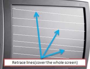
Let us first start by differentiating between retrace lines and just lines:

A)    Lines on Television screen refers to straight lines across the screen like the ones shown on the picture below. Lines usually cover part of the screen but not whole screen.


B)    Retrace lines on the CRT Television screen refers to horizontal lines which covers the whole screen from top to bottom but they are never straight (sloping).


Usually Lines which covers parts of the screen are mostly caused by a fault on the vertical circuit particularly Capacitors ESR gone high. And for Retrace lines they may be caused by the following:-

A)     Blanking Circuit- As electron beam move across the screen of the television scanning from left to right and back usually causes retrace lines, but this never happens thanks to the little known blanking circuit which erase(Blank) those lines which could have been otherwise visible Very fast. But if this block fails then retrace lines will be visible on the screen.

B)      G2(screen) voltage set too high- The Screen Voltage on the other hand if it is increased a lot will causes retrace lines. So next time you change a fly back transformer and find the television is up but the screen has retrace lines try to adjust the screen knob to lower the screen Voltage. The screen will be too bright also.  Usually if the screen voltage increases alone it could point to fly back failure and therefore should be replaced.

C)      RGB Supply too low –On the other hand if the supply to the RBG amplifier is low also usually causes retrace line on the screen and the screen will also be very bright. If this voltage is low it could point to the filter capacitor for that line being faulty(please confirm or replace it directly)