Showing posts with label smps. Show all posts

Saturday, November 19, 2011

SATELLITE RECEIVERS, STRONG SRT 4650 DEAD.

Hello Mr Kimathi.

Amos: I hope you are fine with your daily activities, am fine too. I am receiving now days dead satellite receivers, with many problems, I can only solve small problem like burnt fuse, diode, transistors but it is difficult to repair them because I don’t have enough knowledge about it. All receivers use switch mode power supply, many of these power supplies die, and all these trouble model come from China. How can you help me how to deal with satellite receives, many peoples in my area have

Thursday, May 12, 2011

Relay found in switch mode power supply (s.m.p.s)


Relay found in switch mode power supply (s.m.p.s)

Sometimes in CRT Television s.m.p.s you will find relay in the power supply. In this lesson I would like to have an overview of this component.

First what is a relay? Basically a relay is a switch which is operated electrically.

 The internal structure of a relay is composed of:

1. Coil – work with low current
2. Contacts-Work with high current


Basic relay Circuit


A relay allows one circuit to switch ON a second circuit which is completely separate from the first.

In the example above a low voltage (12Vdc) is used to turn on a relay to switch on a 240V ac main circuit. Please note that there is no electrical connection inside the relay between the two circuits, the link is only magnetic and mechanical.

If there is Zero (0) volt at the Base (B) of transistor Q1. The transistor is open and therefore current is not able to flow from the 12V rail to the Ground and hence the relay contacts are open and the 240V ac Bulb is off.

Now if a Voltage is applied at the Base (B) of transistor Q1. The transistor will close(ON) and the current will start flowing from the 12V rail through the relay coil to the Collector of the Q1 down to the Ground.

When the current flow through the coil a magnetic field is created around the wire and this magnet (electro) will attract the contacts of the relay. Once the contacts closes then the other circuit is switched on and the Bulb light.

With that basic knowledge let us now move on to see how relay are used in switch mode power supply (S.M.P.S) to degauss the CRT tube.

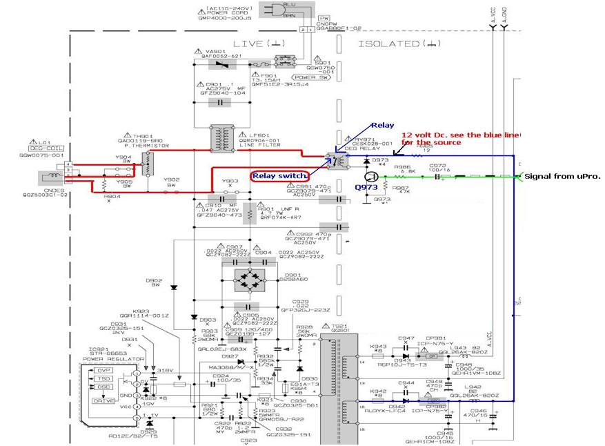
Below is the actual circuit of relay in a JVC Television power supply 


When the Television is first switched on a signal is send from the TV micro processor to the base of Q973 just for a moment (2 seconds). When this signal reaches the base of transistor Q973 the transistor is turned ON and the 12 Volts DC moves to the ground via relay coil. When current flow through the relay coil it behaves like a magnet and relay switch (contacts) is closed. When the relay switch is closed the current flow through the relay on the 240V ac into the Degaussing Coil and the screen is cleaned.

The picture of the actual relay used in this supply


Testing a relay:

Coil: Use your meter set to diode test and you should get a reading if the coil is okay. If no reading then the coil is open and therefore the relay is bad.

Contacts: To test if the contacts are working you need to apply some Voltage (5V dc) to the two pins of the coil and if the contact is working then you should hear a click sound from the relay.

Thanks you guys
Let meet in our next class.

Saturday, March 12, 2011

Replacing CRT television power supply with the universal power supply


Sometimes if you are in CRT television repair you may encounter power supply failure that is too complicated or expensive to repair.

In this video you will be shown how to replace the Television power supply with the universal power supply available cheaply in most market.

Click here…

http://www.youtube.com/watch?v=rh21GpGPFSM

Friday, November 5, 2010

How to troubleshoot CRT Television switch mode power supply problems (s.m.p.s)

Most problems with equipment using switch mode power supply (s.m.p.s) like television and monitor are power related, this is because power supplies runs under considerable stress due to high voltages and current involved around these circuits.

In order to understand how to solve s.m.p.s problem I am going to show you how to analyze common failure mode in CRT television, you can use this principle in repairing CRT monitor too.

Case One: CRT Television Dead

Here dead I mean the set does not show any sign of life, power ON LED is not lighted and nothing happens even after power is switched on.

First confirm the television power cable is not broken inside, you can check this by measuring the voltage across the AC power input connector on the circuit board.


If the voltage is reaching the circuit board, then look for the fuse and see if it is blown, if the fuse is okay check also the surge limiter is open or not.

If these two components are okay then most likely there is no short on the primary side of the power supply.

Short in the primary side of the power supply usually cause the surge limiter or the fuse to blow.

From now on we shall be using the main capacitor negative as the Ground for all the measurements of the voltages on the primary side of the power supply.

I have modified my meter ground probe with a crocodile clip so that I can attach it to the ground point of the equipment I am repairing and therefore I use only one hand to probe the circuit.

This is safety precaution because as you know for there to have a potential difference there must be a connection between the live and the ground.

So if you are using your two hands and incidentally touch the live and the ground then the current will flow through your body and this can be fatal. But if you are using one hand it is not possible.


One thing I have learn in electronics is that if you master doing your troubleshooting using voltage tests you will have an added advantage because in electronics it is not always the component that fail but it could be just a crack on the circuit board that is preventing the voltage to flow or even dry joints and therefore if you concentrate on looking for the bad component you are going to waste a lot of time and end up not repairing the set.

Therefore I encourage you to narrow down to the faulty circuit (area) by using voltage testing only. This one is very fast and valuable method I have come to learn.

Now set your meter to DC range of 1000VDC and use the main capacitor as your ground.

First check the voltage across this main capacitor and if you get around 300 vdc on 220vac outlet or 150 vdc on 110 vac outlet then it is assumed the supply is okay up to the main capacitor.

If there is no voltage at the main capacitor then check backward looking for open component or circuit board cracked or dry joint on the power path.


Be sure this main DC(300vdc or 150vdc) is reaching the power regulator ic collector/drain pin, Now still using the same ground move the positive probe and measure the vcc-IN pin of the power regulator ic.


Depending on the regulator used you can check the correct vcc-IN Supply (start up Voltage) from the data sheet for the ic used from the internet.

These two voltages are very important and if any is missing the supply will appear dead, if the vcc-IN is missing this means there is a open circuit or start up resistor is open.

Follow backward and find what is preventing the start up voltage from reaching the vcc-IN pin.

Another hint: if you see this vcc is less than normal and pulsating there is a possibility that there is a short on that pin, to confirm just lift up that pin and if the voltage increases then it means there is a short on that pin internally and the ic must be replaced.

There is also a filter capacitor for this source usually 100uF/35V, please check the ESR of this capacitor or directly replace it if you don’t have an ESR meter.

There is also a resistor linked to the source pin of this ic called the current sense resistor which sometimes open or change value and this can cause the power supply not to start. Usually it is a very low ohm resistor, less than 2 ohms and around 2 watts so it is a big one.

If up to here you have checked and everything is okay, then you should suspect a short on the secondary side of the s.m.p.s.

First measure for short of any of the secondary diode using analogue meter set to X1, when you measure across any diode on the secondary you should not have two reading and if you get two reading lift up one leg and test again. If you still get two reading then you can conclude that diode is shorted.

Also when using this method and find that the diode has two reading in-circuit and when lifted up you get one reading, it could also mean there is a short on that source (line).

You can follow that source looking for the shorted component; usually the most common components to short are transistors, ics, diodes, capacitors.

Remember when doing voltage testing on the secondary circuit you should be using the COLD GROUND of the set.

The best cold ground to use is the turner ground (out part) or the CRT ground return.


If you find still there is no voltage at the secondary output or the voltage is low, it is the time to substitute for the main B+ Load with a dummy load.

You can make a dummy load by using a 40 watts bulb/250 vac, a bulb holder, crocodile clip and a wire(read and black) and connect them as shown on the picture below.


Now identify the main supply to the fly back called the B+ and disconnect the supply just before the fly back B+ vcc pin. Don’t cut the circuit board to do this just lift up one side of a resistor( high wattage) in series with this B+ voltage or sometime they use a jumper wire just before the B+ vcc pin of the fly back and attach your dummy load between this point and the cold ground.

If the bulb light steadily and you measure between 90 Volts dc to 140 dc depending on the size of the television then you can assume that the s.m.p.s is okay and the problem is on the secondary side.

🔧 Want to take your electronics repair skills to the next level?
Grab your copy of LCD LED television repair guide – a practical, easy-to-follow guide packed with real solutions, pro tips, and step-by-step fixes.
📘 Tap the cover to order now and start repairing like a pro!