As a technician there are test equipment that one requires to get started in electronics which are assumed to be obvious in order to get started in your repair work may it be for hobbyist or professional purposes.
Among them they are others which are not taken seriously as a starter kit but as you walk down the road you find it necessary to add them on your work bench.
When this need arises the technician has an option to go shopping for one or decide to do it by him or herself.
I would like to address the latter group which decides to do it themselves. Although most people would prefer to go this route, you realize that very few people can access the printed circuit board facility around them and hence become difficult for them to get started.
In this article I am going to show you how you can go round this problem by using readily available vero board and achieve the same result like the machine printed circuit board.
As a starter kit (D.I.Y) I have done a template using strip board of the flyback tester based on circuit diagram found on the internet and its working wonderfully for me.
 |

Component values are recorded on their body. Resistors, capacitor, ics , transistors etc for ceramic capacitors the number is written on the body. For ics I advice to use ic sockets instead of soldering them directly to the circuit board.


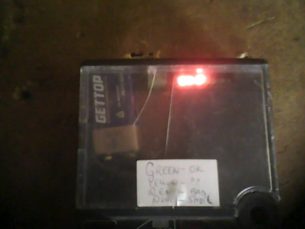 |
| Testing Degausing Coil-Only 3 LEDs ON. |

What is this simple tester capable of doing:-
1. Testing primary winding of flyback transformer in circuit.
2. Testing horizontal yoke coil in crt television /monitors.
3. Testing primary winding of switch mode power supply(all) in circuit
4. Testing the degaussing coil winding in crt television/monitor
5. Testing small DVD motors like the spindle motor ie 2 led lights.
Challenges: as you can see i had a problem of getting a good housing for my project, electronics shops here in my town don't seem to store them therefore i decided to use one of the junk analogue meter housing to serve the purpose.
Feed back: i would love to hear feedback from you fellow technician about your experience on this simple but very important workbench tool.
Additional information for the do it yourself fly back tester
For those who like to use the 9 Volt battery for the power supply please use this adapter to get the 6 Volts for the circuits.

HI Humphrey,
ReplyDeleteCongratulation! You have done a great job in creating a repair blog. I have set two resolutions for this year and one of them will be ready in a month's time. The other one will take another 3 months to complete. There was a saying "A vision without action means nothing but a vision with action you can move the world"
The vision is not necessary have to be in the repair line. It can be any thing.
Consistently provide more info in this blog and I'm sure you will have lots of faithful readers.
All the best to you.
Jestine Yong
http://www.JestineYong.com
HELLO HEMFERY
ReplyDeletePLZ SEND ME PART LIST CONTAINING THE VALUES OF YOUR TESTER
I AM GOING TO MAKE IT
TNX
BEH
Hi Behzad
ReplyDeletemy circuit is based on the circuit on this link
http://www.flippers.com/pdfs/k7205.pdf
if you have any other issue please dont hesitate to ask
Humphrey
Oh! thank you Jestine for your powerful words of Encouragements
ReplyDeleteRegards Humphrey
thank you so much i got all info please give me your e mail address a will send you the picture of my lopt/fbt after Assembly
ReplyDeletergrds
beh
hi behzad, just clisk on my profile and click email and there you go...
ReplyDeleteregards Humphrey
Hi Behzad
ReplyDeleteAre you the Beh from Jestine's ERG site ?
K7205 has been updated to Blue Ringer
http://www.flippers.com/pdfs/BLUE_rt_assembly_manual.pdf
Would you share the board layout after it's done ? A good prototyping board to use is RadioShack Cat#276-168. It has triple holes as well as +ve and -ve supply lines.
hello humphery
ReplyDeleterefer to your colored diagram of above tester
is there a dirct conection between pin 8 small ic to pin 2 big ic also pin 9 big ic with positive side of yello led also pin 7 of big ic to resistor 33k ?
thanks for reply
beh
hi sam
ReplyDeletethank you so much for your link you sent me all is useful
thanx a lot
beh
hi Behzad, i insist on using the template the way it is: i used it exactly the way it and got it working. so i expect you to get the same result to. pls stick on this circuit which i used otherwise you may get confused
ReplyDeletehttp://www.flippers.com/pdfs/k7205.pdf
Also if you click on the circuit.jpg you will get a bigger version if you have not done so.
Again thank you and all the best
Humphrey
There is a lot of good info on this blog. thanks Humphrey Mr quick fix
ReplyDeleteHi Foster, thank you for your encoulaging words, you are most welcome to my blog 24/7
ReplyDeleteKind regards
Humphrey
can i get a circuit diagram of tester.blue ring tester and this tester both are same or what?
ReplyDeletehi Nameless...here is the circuit link.
ReplyDeletehttp://www.flippers.com/pdfs/k7205.pdf
this is the original version by Bob parker, blue ring tester is by ana tek..sure i would say it is one and same thing.
Humphrey
That nice blog and i got something here
ReplyDeleteThanks and most welcome Mobydick
ReplyDeleteRegards Humphrey
good works, can i get ic tester
ReplyDeleteHi Kofesto, Thanks for your compliments. which ic tester are you asking for Kofesto. there are two ic used in this circuit, I.C 1 is LM393 which is a dual comparator and I.C 2 is MC4015/CD4015/4015 which is dual 4-bit shift register.
ReplyDeleteregards Humphrey
I just want to ask other issue which is in CRT TV.My problem with my TV is that it has a horizontal line on the screen.What would be the section affected and what particular component is defective regarding with this symptom?
ReplyDeleteThanks in advance Sir.
Rombu58
Hi Rombu58: copy and paste this link on your browser for more info on this problem:
ReplyDeletehttp://humphreykimathi.blogspot.com/2011/07/gld-television-with-single-horizontal.html?utm_source=BP_recent
Kind regards
Humphrey
Hi humphrey, i need a flyback transformer for my LG TV. Can i used it from other company(ie. sony, samsung, phillips etc).
ReplyDeleteHi Sang, No you can't use fbt from other models..if you can't get the spare in electronics shop near you, try to ask from technicians near you, maybe they may be having a junk lg tv and they can sell to you hopefully.
ReplyDeleteregards Humphrey
nice share. Very useful to technicians like me. and i have already make one of this. Very useful in testing a flyback and chopper transformer
ReplyDeleteHi there,
DeleteThanks for your feedback and glad to note that you have successfully assembled one and working. congrats!
regards Humphrey
Dear Sir,
ReplyDeleteI finally made it today. When I give supply only one red LED lit. I further checking transformer and smps but there is no movement only one LED lit. What I have to do. How can I check circuit with oscilloscope or DMM. Kindly help me.
Mubashir
Hi Mubashir, That is how it should behave when all is ok, to confirm this put one probe on the main capacitor +ve pin and the other probe on the middle leg of the chopper transistor and if all is well all the led should light. regards Humphrey
DeleteDear Sir, Good Day
DeleteI rechecked again but symptom was same. Finally one thing which I didn't assumed that fault was in test probe. There was no connectivity. I changed it and wow all was OK. Its great gadget for my workshop. I am finding now casing for this. Thanks again.
Mubashir
Wonderful..
DeleteGlad to hear your success report Mubashir..
Regards Humphrey
Hi! Humprey,
ReplyDeleteI'm kevin from the philippines province of bukidnon. I just wanna ask a question about the project. The thing is. I've already done making the project the problem is when I turned on the set all leds lit up. I don't know what cause the problem. I'm using a transistor bc557 correct me if this part is the same with the original famous dick smith tester. Thanks humprey.
Hi Kevin,
DeleteThis can be caused by something not done correctly..could be dry-joint, poor soldering, poor connection etc i suggest you check through the circuit slowly and carefully. this is the exact template i used and mine worked first time.
Regards Humphrey
to mr. humphrey
ReplyDeletethanks for the info my friend.........ill mail you if it works for me ,by the way mr. justine wong share me about your diy esr tester that you make....i make one n my world filled with new era in electronics.thank you my friend and if you have new diy to share just mail me at nichang_graywolf@yahoo.com...god bless.....
rey
Thank you & congrats for the great post. As Mubashir said "I finally made it today. When I give supply only first one red LED lit." ; "I rechecked again but symptom was same. Finally one thing which I didn't assumed that fault was in test probe" I checked the probes as prescribed by Mubashir. I am still facing the problem. I am simply using two plain wires as my probes. What I have to do ? Kindly help me.
ReplyDeleteHi Pravin...If the tester is working well this how it should...one red led is always on(serve as a power on led and if when off indicates a short...first try to short the two probes..does the led go off? that is ok..Then do alive test on a live circuit board(TV) one probe on the +ve pin of the main capacitor and the other at the main VCC pin of the control ic or middle leg of the chopper transistor...does all the led light now? care= the circuit should not have power.
DeleteRegards Humphrey
Wow great work Humphrey ,let me try to gather the required components and make myself one I really need it .(Am from Kampala Uganda) jirani
ReplyDeleteHi Kajubi, thanks for your feedback and glad to hear from UG, all the best in making this great gadget and if you have any issue let me know so that i can assist you.
DeleteRegards Humphrey
You are doing the technician community a great favour. Keep up the good work.
ReplyDeleteKumar Gulavita from Sri Lanka.
Thanks Kumar for your feedback, you are most welcome here.
DeleteRegards Humphrey
Hie Humphrey l had a hisense CRT tv it was dead then l fixed it now it working the problem is all the keys for channels and volume and menu are not responding,l measured the voltage across to they key controls is giving 5volts
ReplyDeleteWhat could be the cause
Please can you send me your FBT tester schematic diagram. I love it
ReplyDeleteWELL DONE SIR,AM LATEEF FROM NIGERIA,I REALLY ENJOYED YOUR ELECTRONIC PROGRAM.PLEASE I NEED YOUR HELP AM A BABY IN ELECTRONICS,CAN YOU HELP BUILD ONE FBT TESTER AND LET ME KNOW HOW MUCH YOU WANT TO COLLECT FOR IT.THANKS
ReplyDeleteSir,pls.send me a schematic diagram of flyback tester,it is of big help.thank you very much
ReplyDeleteHi sir good day pls send me a shematic diagram of plyback tester,it is a big help to my working as a technician .thank you very much sir and GOD BLESS U AND UR FAMILY
ReplyDeleteHi Humphrey. I have built the flyback tester some time ago, however I have yet to test it and put it in an enclosure. I have one question though, how do you test it? The original manual mentions a test coil (which I think was supplied with the kit). Is this necessary or should it just work?
ReplyDeleteThanks, I'm going to build this hopping I can do it without diagram, good day
ReplyDeleteHi Humphrey I have built the fbt sometimes back,it was having one red light up when switched on but now they are two red led on whenever it's switched on and when I sort the probes they go off is that how it should work. George from MSA kenya
ReplyDeleteHi from Australia. I'm the guy who designed the Dick Smith Electronics flyback tester you are all talking about. I never expected it to become well known, or that people would be making copies of it even in Africa. :) The Anatek flyback tester is not the same design and it is not better than the original Dick Smith tester.
ReplyDeleteThanks for your feedback Bob and glad to hear from Australia. I was trained by a friend of mine from Australia Mr Ron Bertrand from the Radio and electronics school of Australia...Kindly let me know if you can share an article on this blog on how you came up with this incredible tester..my contact is +254 733 475 040( whatsup)
DeleteHi again Humphrey. There really isn't much of a story behind this tester. Back in the 1990s I was doing repairs of domestic electronics including some CRT colour TVs, and finding it hard to clearly identify flyback transformers which had broken down internally. Knowing that short-circuits between turns will destroy the "Q" of resonant circuits, I did a lot of experimenting with feeding pulses into flyback transformers and seeing the results on the oscilloscope. I wanted the readout to be on a LED "bar graph" and it took a long time to think of using a shift register to do it. Eventually the project got published in Electronics Australia magazine, and Dick Smith Electronics started selling kits for it. All the information about the circuit and how to use it is in the kit notes which can be downloaded from http://www.zilogbob.com/lopt_tester/k7205.pdf I'm very happy that other technicians are still finding this project useful after nearly 30 years!
ReplyDeleteThanks again Bob, this is the circuit diagram I used to construct mine, and was my first blog post 14 years ago...
Delete